Monday, Feb 1, 2016

Windows Server 2012 Hyper-V Failover Clustering - Part 2: Prerequisites
After we covered the basic concepts in the previous post, it’s now time to start working on the actual implementation. We will start with the high-level overview of the system structure, and than move on to the installation of prerequisite features.
As we saw previously, DNS can hold multiple records for the same domain name and return a list of IP addresses for a single name. Therefore, when a browser issues a request for a particular URL, it can get a list of corresponding IPs. It will try to access them one-by-one, until a response is received. These IP addresses do not point directly to our application servers - they point to load balancers/reverse proxies that are balancing the load on a granular level, using the default round robin algorithm. All of the servers and other system components (Web, database, SAN, …) are placed in a private network and can only be accessed by other servers within this network. Load balancers are accessible via the Internet and also linked to the private network.
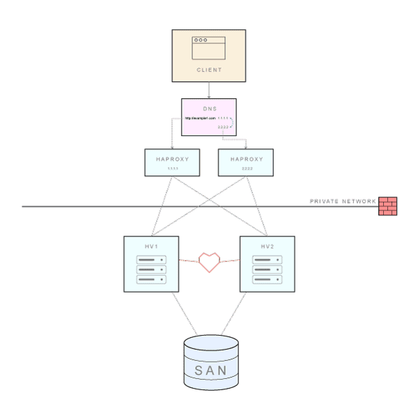 Overall system architecture (click to enlarge)
The basic setup includes two servers running Hyper-V hypervisor and a Storage Area Network (SAN) as a shared storage mechanism. Additional Hyper-V servers can easily be added to achieve better scalability. In our scenario, each server contains 4 Gigabit network adapters (NICs) and one Fibre Channel adapter (or host bus adapter, HBA). This FC adapter is used to connect with the SAN.
Hyper-V clusters require shared storage - in one way or another - that each Hyper-V host can access for storing highly available VM’s. Apart from FC SAN arrays, you can use iSCSI devices, SAS JBOD enclosures, and SMB 3.0 shared folders on Windows Server 2012.
We are creating multiple volumes on our SAN that will serve different purposes:
- SystemStorage volume will hold the system disk of our database server.
- DatabaseStorage will be used to store PostgreSQL databases.
- FileStorage will be exposed to the application servers as a central shared location where users can store and share files.
- Witness will be used for failover cluster quorum configuration
Basic installation and networking
For a start, you will need to add the Hyper-V role to the servers. In Server Manager - Manage menu, click Add Roles and Features, select Role-based or feature-based installation, select the appropriate server, and pick Hyper-V on the Select server roles page. Leave all the default options on subsequent pages, and the Hyper-V role will get installed.
Is is always a good idea to use at least two separate NICs in failover clustering scenarios: the public interface is configured with the IP address that will be used to communicate with clients over the network, while the private interface is used for communicating with other cluster nodes (“heartbeat”). We will use an additional NIC for backup purposes - although this is not absolutely necessary, it will offload the traffic caused by regular backup tasks from the public interface. This leaves us with one free NIC, and we’ve decided to team two NICs on a main public interface. NIC team is basically a collection of network interfaces that work together as one, providing bandwidth aggregation and redundancy. It is easy to team NICs in Windows Server 2012, so I will not provide a step by step instructions on how to do that: here is an excellent article on NIC teaming that will guide you through the process. It is not a mandatory step for setting up a failover cluster.
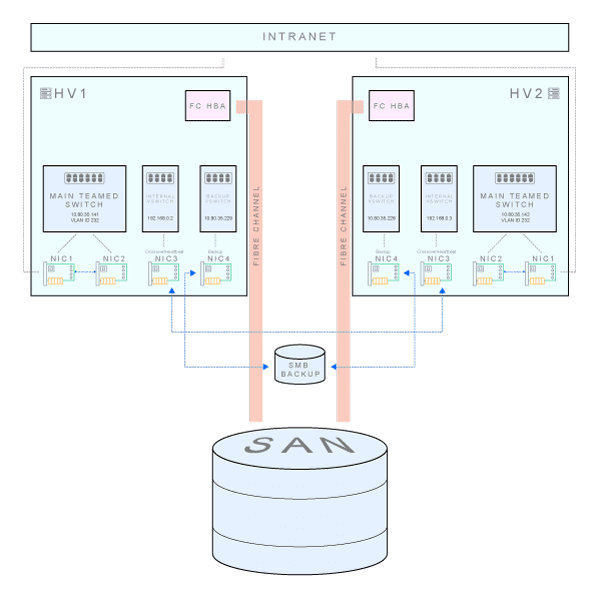 Network connectivity: physical NICs and virtual switches inside each Hyper-V box (click to enlarge)
In this example, we are using an A class private network with 30 hosts. Let’s say that the subnet starts at 10.80.35.128, and the subnet mask is 255.255.255.224. Gateway is located at 10.80.35.129, and broadcast address is 10.80.35.159. Backup share is located on a separate subnet. Here is how we set up the NICs on the HV1.
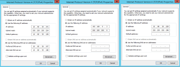 TCP/IP properties of server NICs - from left to right, main teamed NIC, internal heartbeat NIC and backup NIC (click to enlarge)
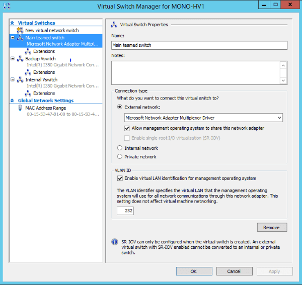
Now it’s time to go to the Hyper-V Manager. Right click on the server name and choose Virtual Switch Manager. We’ve created three external virtual switches (New virtual network switch -> External), each connected to one of the NICs (main teamed NIC, internal heartbeat NIC and a backup NIC). The Hyper-V Virtual Switch is a software-based layer-2 Ethernet network switch that is used to connect virtual machines to both virtual networks and the physical network. This is how network connections look after this step. Three Hyper-V virtual Ethernet adapters have been automatically added during the process of virtual switch creation, one for each switch.
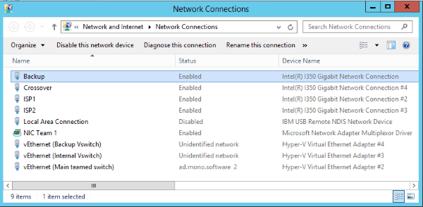
An important concept has been put at work in the Virtual Switch Manager. As you can see, the main switch uses a VLAN ID to help us create multiple networks on a single NIC/switch. In our case, the same NIC and virtual switch are used to connect both to the private network (that’s VLAN ID 232) and to public Internet (that uses another VLAN ID). Without it, an additional NIC would be needed to directly connect to the outside network - that is sometimes needed for additional servers (unrelated to the scenario we are describing here) that are not placed behind the load balancer. Other virtual switches do not use VLAN identification.
Active Directory integration
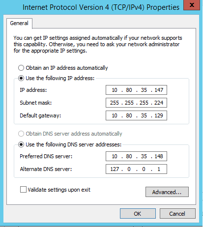
Windows Server Failover Clustering has always had a very strong relationship with the Active Directory. This means that we need to set up the domain controllers before we proceed with the installation of the Failover Clustering feature. While it may be tempting, there are actually numerous reasons why not to install the domain controller role and the Hyper-V role in the same physical instance of Windows Server. This means that we will first create virtual machines for domain controllers (primary and secondary) on both hypervisors, HV1 and HV2. For this showcase setup, our domain is called ad.mono.software, with domain controllers dc1.ad.mono.software and dc2.ad.mono.software. Since domain controllers will also run a DNS service, pay particular attention to configuration of the network settings. Below is an example of the network configuration for DC1 - its primary DNS server points to DC2, while the secondary DNS is set up with the loopback IP (and vice versa on the DC2).
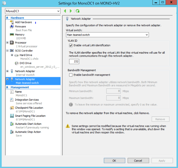
When adding the network adapter to the VM, we have connected it to the main teamed virtual switch in the Hyper-V Manager, and checked “Enable virtual LAN identification” in the VLAN ID section. The VLAN identifier is set to 232.
The domain controller installation is a relatively straightforward process, and there are many step-by-step instructions - like this one. In a nutshell, go to the server manager, select Add roles and features, choose Role-based or Feature-based Installation, select a server on which you would like to install the AD DS, select Active Directory Domain Service, click on Add Features button when asked for related tools, click Next button a couple of times and that’s it. After Active Directory Domain Services role has been installed, you can promote the server to a Domain Controller from the main page of the Server Manager. You will choose Add a new forest and enter your domain name on the primary domain controller (in our case it is DC1), and additionally select that you want to add DNS server and a Global Catalog. The process is very similar on a secondary domain controller, but this time you will choose Add a domain controller to an existing domain.
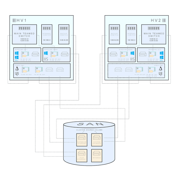 Detailed functionality, connectivity and storage arrangement per virtual machine (click to enlarge)
The end result is shown above. We have three virtual machines running on each Hyper-V box in a failover cluster: a domain controller (Windows Server 2012 R2), an application server (Windows Server 2012 R2 with IIS and our ASP.NET application) and a database server (Ubuntu Server 14.04 with PostgreSQL 9.5). Note that the database server has been configured as a fault tolerant, highly available VM clustered role. This means that it will be active on only one cluster node, and other nodes will be involved only when the active node becomes unresponsive, or when migration is initiated for another reason. While database server’s system and data storage disks are stored on a shared storage, only one node will access it at the time. Remember that by default PostgreSQL does not support multi-master or master-and-read-replica shared storage operation. That’s why we use shared disk failover, allowing rapid failover with no data loss.
Domain controllers and application servers run on both nodes without sharing state information.
That’s it regarding the prerequisites and the overall system architecture. My next post will describe how to install Windows Failover Clustering Feature and our application and database servers.